
A defined water-quality basis
Twelve client-provided indicators established the design basis, covering pH, turbidity, conductivity, hardness, alkalinity, chloride, iron, sulfate, ammonia nitrogen, COD, bacteria and organic phosphorus.
Starting with the client’s outlet-water requirements, EFMC coordinated process engineering, electrical automation, civil and piping works, data-center-side interfaces, construction and commissioning as one turnkey cooling-water treatment project.
Client requirement
The client needed a complete cooling-water treatment system for an AI compute facility. The treatment process had to meet the specified outlet-water criteria and connect cleanly with power, controls, buildings, pipelines and the operating data center.
Twelve client-provided indicators established the design basis, covering pH, turbidity, conductivity, hardness, alkalinity, chloride, iron, sulfate, ammonia nitrogen, COD, bacteria and organic phosphorus.
Process design, electrical automation, civil works and piping could not be developed as isolated packages; equipment footprints, utilities, signals and tie-in points had to agree before construction.
The required endpoint was not separate skids or drawings. It was an integrated installation that could be commissioned, monitored from the supervisory system and handed over as a working plant.
Design basis
The supplied outlet-water schedule defined twelve parameters. The values below are selected design criteria from that schedule, not claims of field-test performance.
Specified design outlet-water range.
Design value supplied for process selection.
Specified electrical-conductivity design value.
Specified total-iron design value.
Specified calcium-hardness design value.
Specified total-alkalinity design value.
Turnkey delivery path
EFMC organized the project as a continuous engineering and delivery sequence. Each stage produced the conditions needed by the next, reducing gaps between design documents, fabricated equipment, site interfaces and operating logic.
Integrated engineering
The design package coordinated plant footprint, equipment arrangement, main electrical circuits and automation interfaces before work moved to the site. Fabrication then followed the same system boundaries used in the drawings.
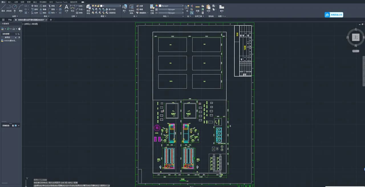
Equipment, tanks, operating clearances and service areas were coordinated in the workshop layout before construction.
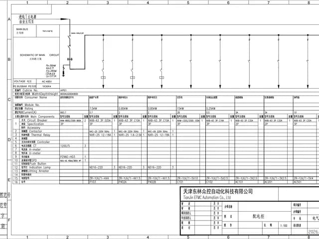
Pumps, treatment equipment and auxiliary systems were incorporated into a documented electrical and automation architecture.
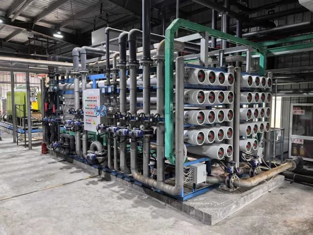
Membrane housings, pumps, valves and manifolds were assembled as maintainable process units before delivery.
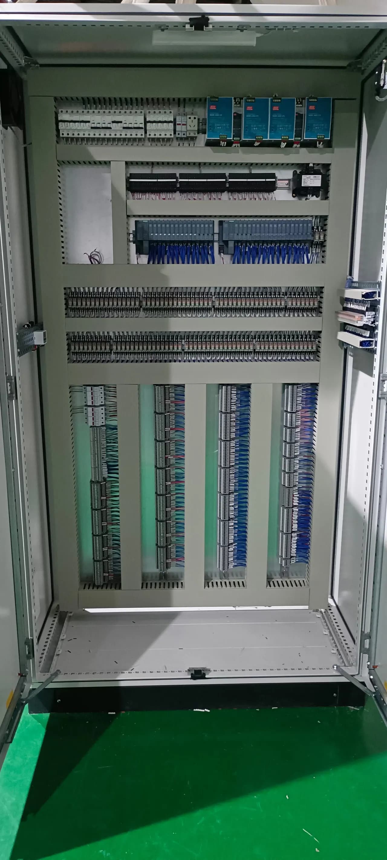
Distribution, control and signal components were organized into the panel that would connect field devices with supervisory control.
Data-center-side construction
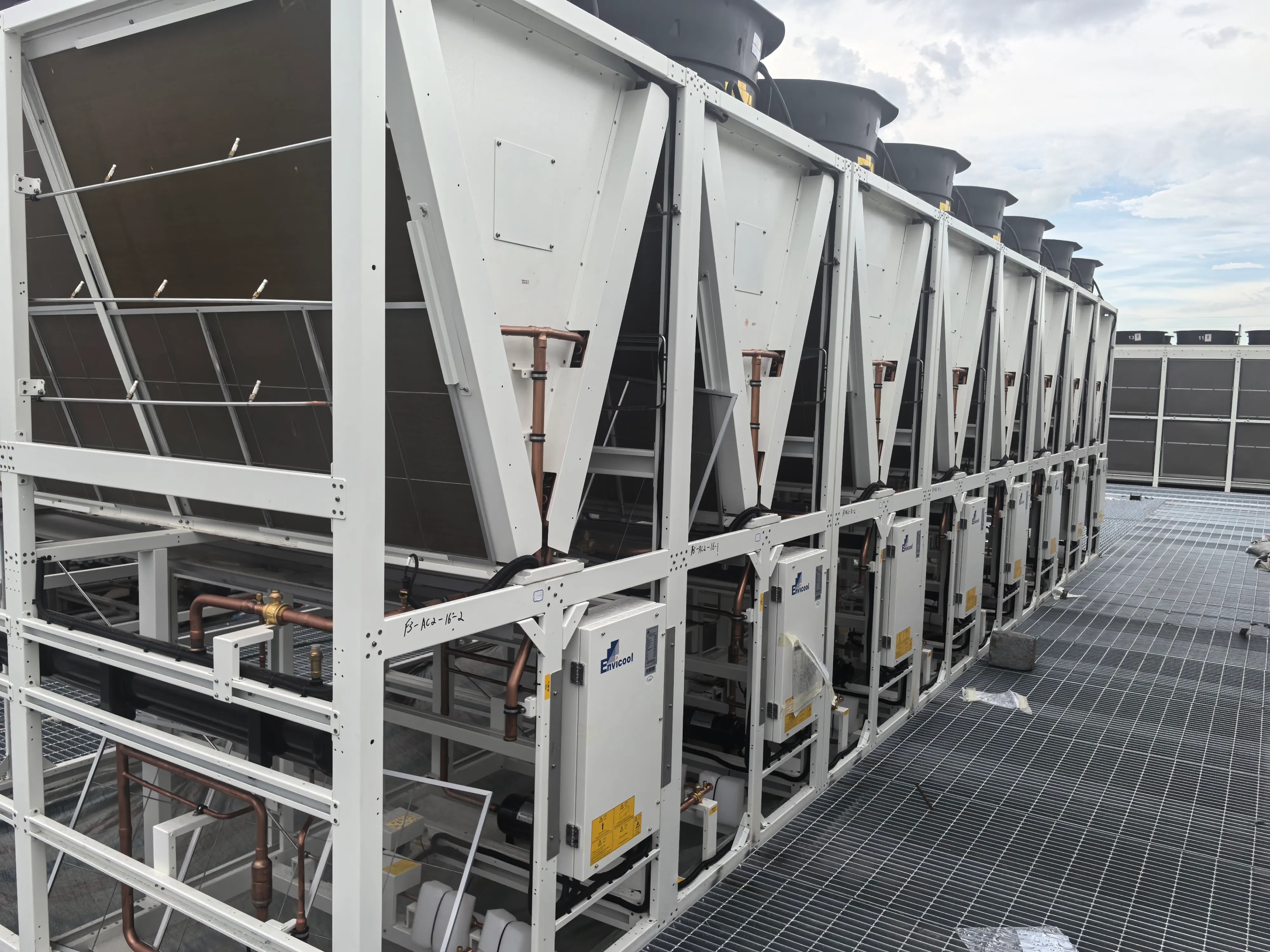
Site work extended beyond the treatment workshop. Pipe routes, terminal connections and heat-rejection equipment on the AI compute side had to align with the water plant, construction sequence and final control strategy.
Completed treatment plant
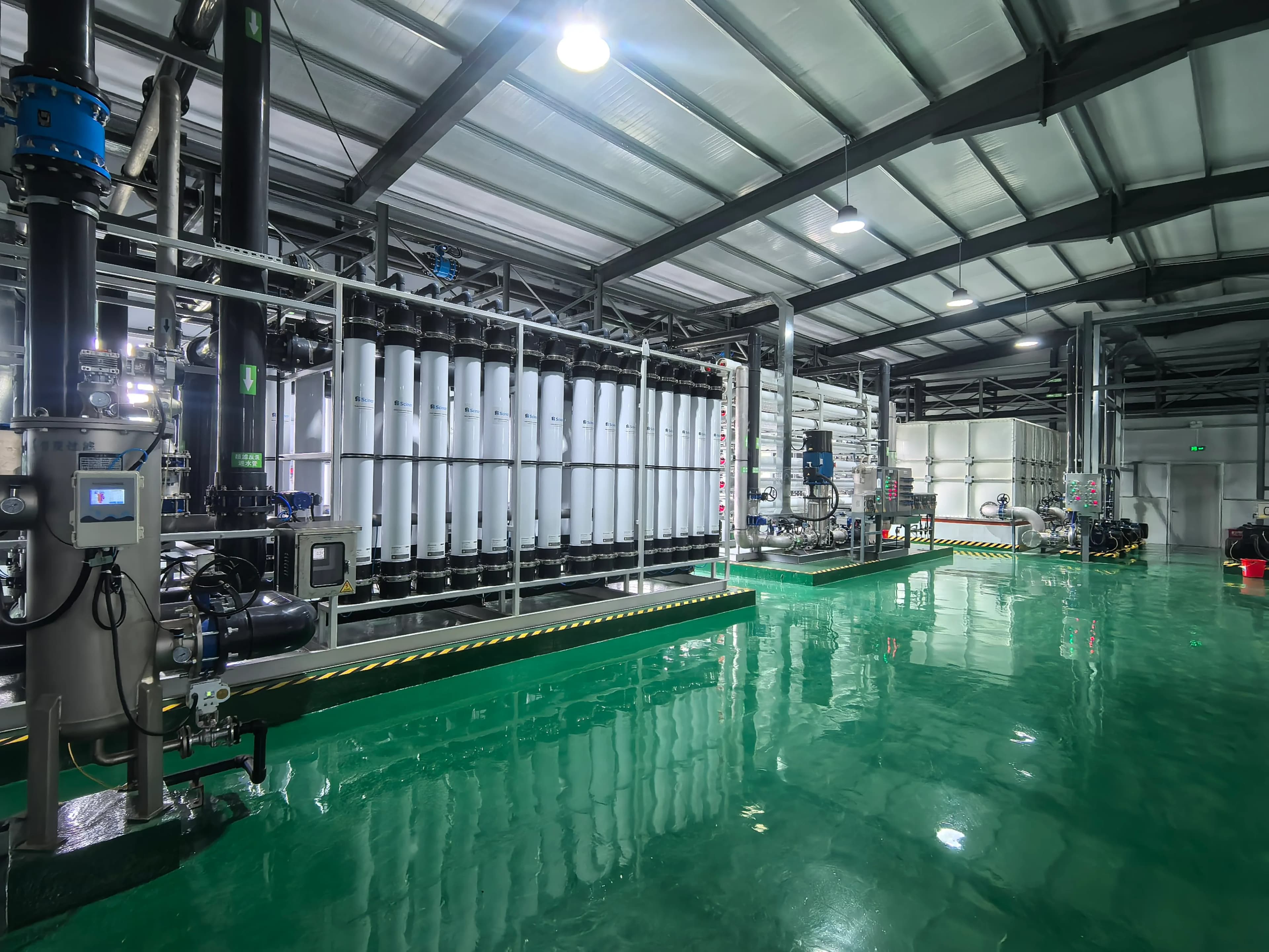
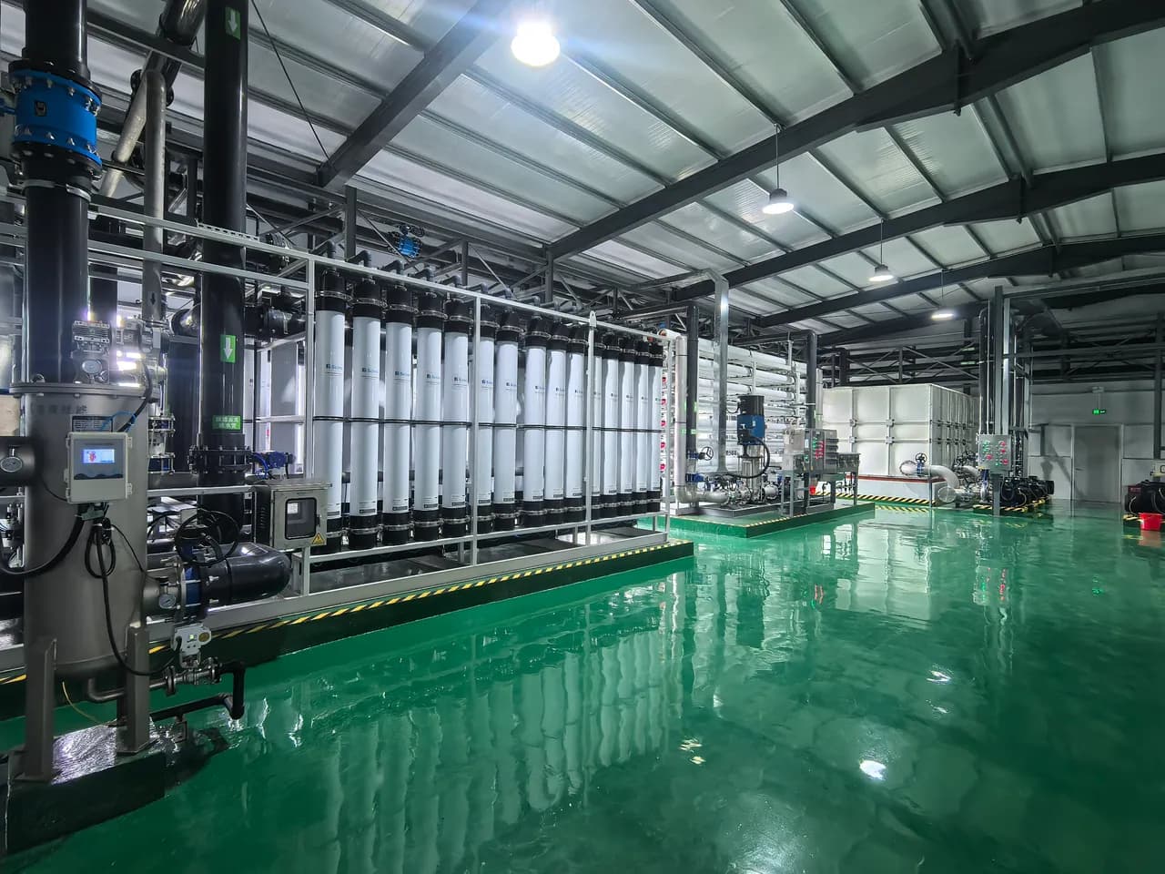
The finished installation brings pretreatment, ultrafiltration, reverse osmosis, dosing, chemical cleaning, pumping and operations into a coordinated plant environment with clear access around major equipment.
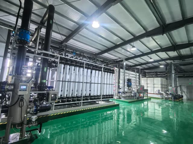
Parallel membrane modules form the front-end separation stage and connect to automated production and cleaning routes.
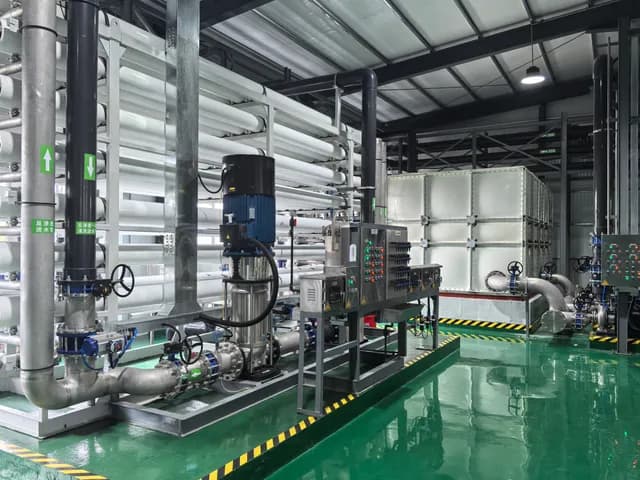
The RO stage follows ultrafiltration and provides the principal dissolved-solids treatment step in the documented process.
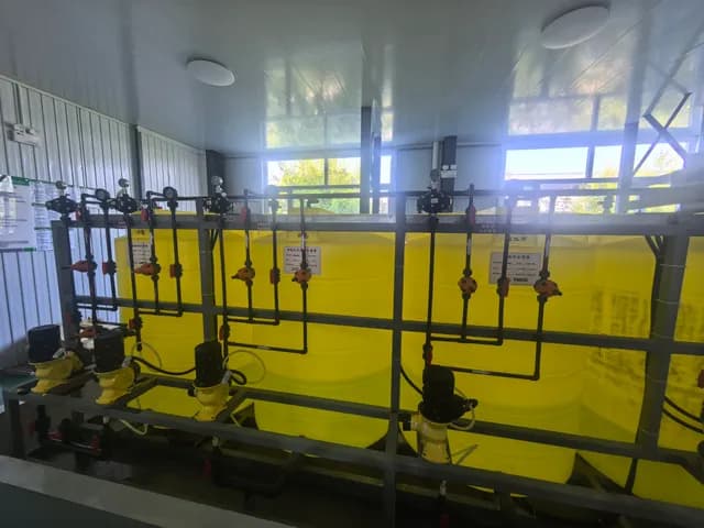
Dedicated tanks and metering pumps support the chemical conditions required by the treatment and water-supply processes.
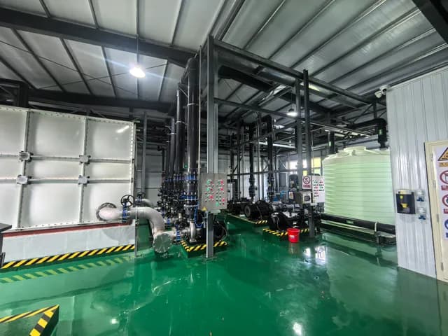
Cleaning circuits and pump equipment were installed alongside the main trains to support operation and maintenance.
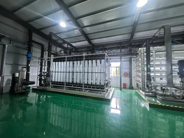
The completed workshop organizes major treatment units, circulation paths and maintenance access as a single operating environment.
Walkthrough
A single pass through the completed workshop — pretreatment, ultrafiltration, reverse osmosis and the dosing skid, in the order the water moves through them.
Supervisory automation
The supervisory system separates the process into ultrafiltration, reverse osmosis, dosing and supply views while keeping operating states visible on a shared status panel. Field devices, valves, pumps, tanks and key process readings are represented in the same control environment.
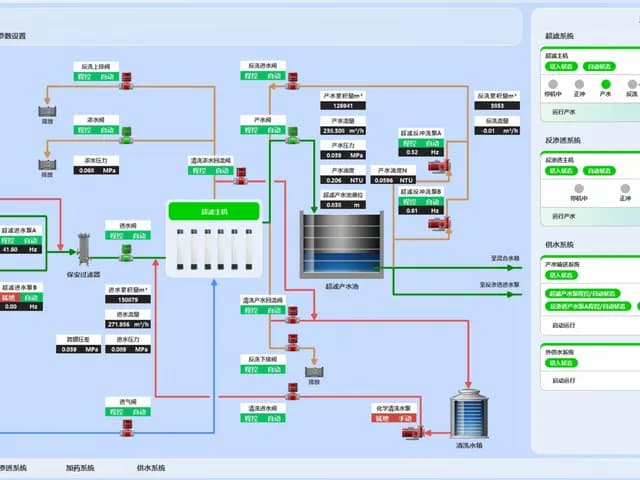
The screen presents the UF flow path, pump and valve states, water levels and selected operating values.
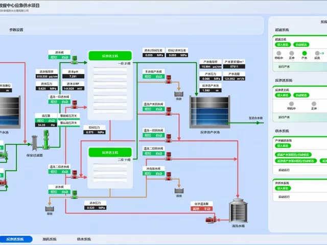
Operators can review feed conditions, membrane-stage routing, production flow, conductivity and tank status from one screen.
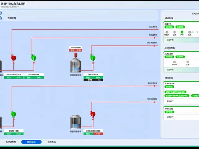
Dosing tanks, mixers and metering pumps are presented by process function, with automatic and manual states visible to operators.
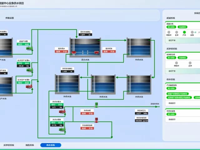
Tank levels, transfer pumps, external supply pressure and conductivity complete the visible path from treatment to use.
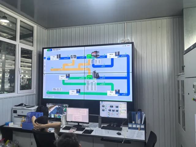
The finished operations station places the integrated process display in the environment used for daily supervision.
Project outcome
The completed scope combines the treatment workshop, UF and RO trains, chemical dosing, cleaning and pumping systems, electrical automation, supervisory visualization and data-center-side cooling connections. Because the package contains design criteria but no formal commissioning test report, this case describes the delivered architecture and visible operating system without adding unsupported performance claims. The result is a coordinated plant delivered around the client’s requirements rather than a collection of independently supplied components.
From the first water-quality target to the final operating screen, one team remained responsible for the whole system.